2. The 2SA9 series offers two options: mechanical torque protection and electronic torque protection (optional).
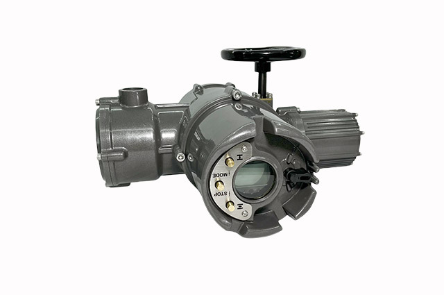
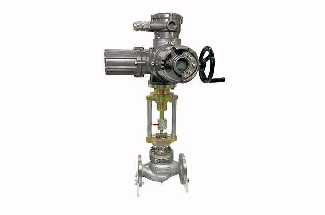
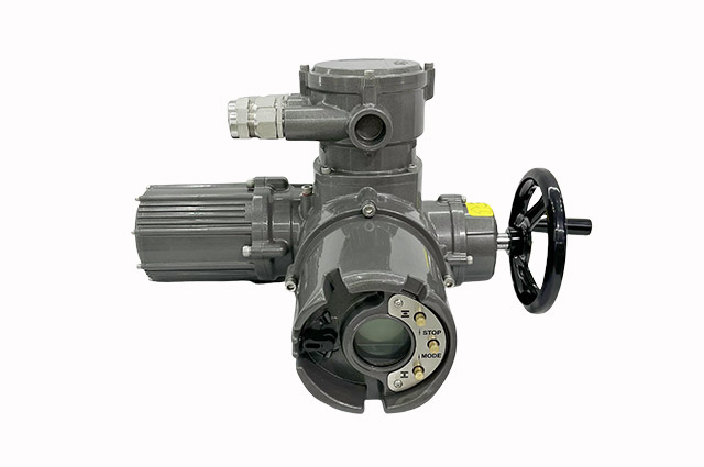
3. The 2SA9 series adopts a semi-automatic manual-electric switching method. By pushing the handwheel, it switches to manual operation, and at the same time, the motor circuit is cut off to prevent motor maloperation and safety accidents. After manual operation is completed, simply release the handwheel, and the actuator will automatically return to electric operation.
4. Non-intrusive design: It adopts non-contact magnetic steel control sensing components, enabling non-intrusive user debugging. This effectively prevents dust, moisture, etc. from entering the machine interior, protecting the motor and control circuit from erosion and enhancing stability.
5. Precise positioning: The magnetic control absolute value encoder is adopted to achieve accurate stroke positioning and position control. Power outages and disturbances will not cause valve position loss.
6. The human-machine interface adopts a high-brightness and high-contrast LCD display screen. An optional full Chinese menu is available for Settings and debugging.
7. Infrared remote control: Use an infrared remote control to debug, operate, set parameters or query the actuator. Avoid opening the cover for parameter setting and debugging to effectively prevent moisture and dust from entering.
8. Phase loss protection: It has the functions of power phase loss and output phase loss protection.
9. Automatic phase sequence correction: The rotation direction of the actuator can be freely set. It can automatically correct the phase sequence of the power supply. There is no need to consider the phase sequence of the power supply when wiring.
10. The signal can be freely configured, with a maximum of 6 contact signals output. There are 12 state signals for users to choose from, and each signal can be freely defined. (Optional
11. Control mode: Multiple remote control methods are available for users to choose from. All remote control signals are electrically isolated from the internal structure.
12. Electronic braking: It adopts an electronic energy consumption braking method to prevent the motor from idling. The braking intensity can be set, with no mechanical wear and no maintenance required.
13. Fault diagnosis: The internal CPU continuously collects various information of the actuator, monitors the operating status of the actuator, and issues various alarms and fault information through self-diagnosis, facilitating users to handle faults promptly and quickly.
14. Emergency operation: Prioritize the response to "emergency" switch input signals. Once effective, the actuator operates to the pre-set emergency position. (Optional
15. The debugging is convenient. Just set and record the terminal position of the valve's opening and closing directions, and the debugging work can be completed.
16. Motor overheat protection: It adopts a low-inertia high-speed motor. After starting, the motor can quickly reach the peak torque and has an overheat protection function.<
| Ambient temperature | -30℃ to +70℃ (Special orders can be accepted) | |
| Work format | Adjustable type: S4 or S5 periodic intermittent operation mode, with operation cycles of 300c/h, 600c/h, 1200c/h, and a minimum load duration of 10%. | |
| Switch type: S2-15 minutes, short-time operation mode. | ||
| Power supply | Three-phase AC: 340-690V AC, single-phase AC: 110-240VAC | |
| Dc: 24-96V | ||
| Protection grade | IP 68 | |
| Positional repetition deviation | ≤ 1 % | |
| Torque repeatability accuracy | ≤ 1 % | |
| Connection standard | JB2920,GB/T12222 | |
| Basic error | ≤ ± 1 % (Adjustable section type ) | |
| Return difference | ≤ 1 % (Adjustable joint type) | |
| Explosion-proof grade | Ex db llB T4-T6 Gb,Ex db llC T4-T6 Gb | |
| Terminal | Terminal type | 28芯 |
| Contact point | 500VAC/DC 16A | |
| Cross-section of the conductor | ≤2.5mm² | |
| Input signal | Switch quantity input | Passive contact |
| Electric voltage 2 4V DC ± 10 % | ||
| Pulse width > 2 00 m s | ||
| Photoelectric isolation | ||
| Analog input | DC 4 -2 0mA | |
| Input resistance ≤ 2 50 Ω | ||
| Output signal | Switch output | Output formula: ≥4 passive contacts |
| Capacity: 30 VDC/ 250 VAC 5A | ||
| Position feedback output | DC 4 -2 0mADC | |
| Load capacity ≤ 750 Ω | ||
| Linearity ≤ 0 .3 % | ||
| Control | Dead zone | Adaptive |
| Bus | MODBUS bus, PROFIBUS bus, HART bus, FF bus | |